Fixing a Mill Drill Stand

If you listen to the podcast you already know that I purchased a Rong Fu Mill Drill.  While some people have issues with the round column, the mill drill is a significant step up in machine capacity and machining performance when compared to the X2 mini mill.

For those unfamiliar, the Rong Fu Mill Drill looks to be a heavily modified drill press.  There are several size variations, but most utilize a R8 tapered spindle with provisions for a draw bar.  The dovetail table has a relatively large travel of about 450 mm (over 17″) and 200 mm (just under 8″).

While there is much debate on the origins of the Taiwanese mill drills that started showing up in the 1970s, the most probable explanation is they are simply rather crude copies of the Fehlmann mill drill machines.  Fehlmann is a Swiss machine tool manufacturer and they still build a number of mill drill machines, although I suspect you if have to ask the price you cannot afford them.  Besides the very similar appearance, the main reason I think the Rong Fu mill drills are copies of the Fehlmann is primarily because of the tapered gibs on the Rong Fu table.  Fehlmann being a Swiss machine tool company in and of itself is another telling reason why they were copied.

Round column mills are not just limited to two companies.  Emco also  manufactured several round column mills around the same time as Rong Fu started.  A German company  also manufactured a nice home shop mill drill branded as Ixion around the same time or slightly before the Rong Fus started flooding the home shop market.

The Rong Fu mill drill I purchased came with the typical flimsy tuna can stand that is oh so common on import machine tools.  I did not purchase the machine new and the previous owner was selling the stand with it, otherwise I would have passed on the stand and just built one.  Initially I was going to weld up a new stand out of 2×2 steel tubing, but then I thought could I just dump a bunch of concrete in the bottom and kill 2 birds with one stone; adding weight and rigidity?  That and I find concrete a very useful engineering material in the home shop from previous antics.

And that’s exactly what I did.  For less than $75 and one day’s home shop work, which is less than what the material alone would have cost for a tubing stand, I now have a rigid machine tool stand.

I’ll be posting further on the mill drill as I use it, but so far it has been a great addition to the shop.

Concrete Bench for the Lathe

For my latest project, I made a concrete bench out of standard precast concrete blocks that are easily sourced.  I filled them up with cement and steel reinforcement, grouted a piece of granite countertop on (to give a nice flat surface), and anchored my import lathe to it using sleeve anchors.  I made a video of it here:

I also made a video of a quick analysis I did of the stiffness and damping properties of concrete and found concrete to be a great material to make a lathe bench out of:

It turned out well.  I originally was going to build a steel bench out of 2×2 tubing to move the lathe to as the wood bench gave significant grief when trying to get the twist out of the bed.  I then started thinking outside of the traditional box, and thought, hey what about concrete.

Now my lathe is pretty short – if you had a longer lathe you might want to support the granite countertop more with perhaps some steel bolted between the 2 supports.

I plan on making some shelves for below the lathe yet in between the 2 blocks.  It was a fun project, and I learned a fair bit about cement and concrete in my reading.  If you want to improve the damping even more, there are many studies on adding rubber pieces to the cement.  You can also add steel wool to significantly improve the strength.  Simple standard concrete alone though has the damping properties of cast iron.

Yes I can’t really move it, and I thought a lot about this, but I really don’t move my machines that often anyway.

The performance of the lathe is significantly improved, it is like day and night really.  I didn’t think it would make that much of a difference.  Some slight shimming maybe required yet to get the last small amount of taper out (or it could be another issue – I haven’t investigated any further yet as the taper at this point is way better than the .003″ over 3 inches I was getting before).

Here is a picture of the bench itself:

concretebench

And with the lathe (I previously made a drip pan the lathe is sitting on):

latheonbench

It didn’t take that long to do – not significantly longer than any other bench construction method.  Plus I didn’t’ have to deal with steel distortion and residual stresses due to welding – something that can be a significant issue.


Bench Grinder Balancing with a Smart Phone

Disclaimer:  Bench Grinders are dangerous.  If you improperly mount the grinding wheels they will explode and hurt or kill you.  If you mount damaged wheels they will explode and hurt or kill you.  Find someone to help you or educate yourself thoroughly on appropriate safety before attempting any work on a bench grinder.  Attaching weights to the bench grinder to balance it is not a straightforward task.  The weights could fly off when the machine is running and cause serious injury.  Do so at your own risk!

There with that out of the way, I found another use for my smart phone in the shop: dynamically balancing my bench grinder.

Here is my bench grinder.  It is a 8″ Ryobi from Home Depot.  It spins at 3600 rpm which is a little fast for HSS tool bits but it works and has plenty of power for what I do.  Of course I removed the wheels it originally came with and purchased 2 new  CGW Abrasives wheels from a reputable tool supply house in my area.

Ryobi_BenchGrinder

Before we move on to balancing, let me say that I re-machined the wheel mounting hardware that came with my bench grinder so it was flat.  I made new grinding wheel bushings for the wheels so they were mounted as true as I could get them.  I also trued up the wheels with a diamond tipped dressing tool similar to this one: http://www.mcmaster.com/#grinding-wheel-truing-tools/=132y8pr

My bench grinder still vibrated.  It wasn’t serious, and didn’t affect the grinding of high speed steel tools, but it bothered me.  It was an inexpensive bench grinder, and I could go out and by a more expensive one, but most of the new ones all come from China anyway, and I was getting sick and tired of searching for sale posts for a good used Baldor for a reasonable price.  So I decided to see if I could at least make things a bit better.  I also know that surface grinding wheels are balanced when they are mounted.

First you need to know the mass of the entire grinder.  I used a baby scale that we have around the home.  Of course I had to remove the grinder from my grinding table.

Ryobi_BenchGrinder_Mass

I then determined the resonant frequency of my grinder.  To do this you need to mount your smart phone to the bench grinder.  I used zip ties, again.  You can see some of my other ‘cell phone’ engineering on my other page where I analyzed my mini mill using my smart phone:  https://thecogwheel.net/2016/06/27/x2-mini-mill-vibrations-and-chatter/

Ryobi_BenchGrinder_withcell

Next step was to determine the  natural frequency of the system. With the grinder off, turn on your accelerometer app and tap the grinder with a dead blow hammer.  I exported the results and took a look at the response in Excel.  Here is what the chart:

BenchGrinder_NaturalFrequency

Now you can see the wave is a little choppy.  This is due to my smart phone’s accelerometer limitations.  You could do much better with a higher quality accelerometer programmed using a micro controller (a Arduino works well!) but that wasn’t the point of what I was trying to do.  I wanted to see if my smart phone would provide useful information because it is easy to use!

From the graph I found the period of the vibration to be 0.032891 seconds.  The inverse of the period is the frequency, which is 30.403 Hz.  Note this is the damped frequency, denoted Wd.  From this point on some math is involved, you can view it in the spreadsheet posted below.  If you want me to detail the math used, send me an email.  Using the data the following was calculated:

Damping Factor 0.3890832
Natural Frequency 33.00449108 Hz
Natural Frequency 207.3733334 rad/s
Natural Frequency 1980.269465 rpm
Weight 39.996 lbs
Mass 18.18 kg
K (spring rate) 781807.2555 N/m
C (damping) 47.7799696 kg/s

As we can see, my bench grinder’s natural frequency is around 2000 rpm.  This means that it must accelerate through the natural frequency when it starts up.  I plotted the a startup of my bench grinder using my cell phone to confirm my results.  The very right of the chart shows the grinder running in steady state, or 3600 rpm.  You can see the response is stable and repetitive at the right hand of the graph.

BenchGrinder_StartupPlot

Not so good!  Now this is a rotational imbalance problem.  Essentially a unbalanced mass is causing the entire system to oscillate.  This oscillate is the worst at the resonant frequency, but the unbalanced mass also contributes to the oscillation during steady state operation, in our case 3600 rpm.  Can we calculate what this unbalanced mass is?  Of course we can!

First we need to calculate what the response displacement is.  To do this you need to find the maximum, vibration amplitude during steady state.  My grinder had a maximum acceleration amplitude of 10.42 m/s^2 during steady state operation.  To calculate what the displacement is you need to divide this number (subtracting gravity first!) by the rotational speed squared (converted to radians per second).  You do all this and  found my displacement to be 0.004292 mm.  Once we have this, we have all the information we need to calculate what the unbalanced mass times radius factor (mR)  that is causing this vibration.

We need to solve the following equation where X is the displacement, mR is the mass x radius due to the unbalanced mass, M is the mass of the entire system, r is the frequency ratio and zeta is the damping factor:

Displacement_EquationAgain some math is involved, you can view it in the spreadsheet posted below.  If you want me to detail the math used, send me an email.  Using the data the following was calculated:

Max Amplitude 10.42 m/s2
Gravity 9.81 m/s2
Absolute Difference 0.61 m/s2
Rotational Frequency 3600 rpm
Rotational Frequency 60 Hz
Rotational Frequency 376.9911184 rad/s
Frequency Ratio, R 1.817934409
Displacement, X 4.29208E-06 m
Displacement, X 0.004292078 mm
Unbalanced Mass x Radius, mR 6.38521E-05 kgm
Unbalanced Mass x Radius, mR 0.063852078 kgmm
Radius of Required Mass 20 mm
Required Mass 0.003192604 kg
Required Mass 3.192603888 grams

So there, we now know how much mass we need.  Since I didn’t have any way to use my cell phone to figure out where the unbalanced mass was occurring  (this would require a some sort of method to determine phase of the wave from, such as a proximity sensor trigger), I decided to stick on trial weights and move them methodically around the wheels and watch the response on my smart phone.  After several tries I found a spot that was close to where it should be and proceeded to stick on the weights.  I used little washers, and I placed them on each wheel.

I used the following mounting tape:

BenchGrinder_MountingTape

I mounted the weights on each wheel, covered them with high strength tape, and let it sit overnight (according to the tape’s instructions) to harden up.

BenchGrinder_MountedWeight

I put the covers all back on and started it up.  It ran much smoother, and my cell phone’s accelerometer showed significantly less vibration.  I couldn’t get the weights placed perfectly to get rid of all vibration, so some is still present.  But it is a lot better than it was.

BenchGrinder_CellOutput


I plotted the results of my grinder starting up and overlaid them over the results before I added the mass:

BenchGrinder_StartupPlotAfter

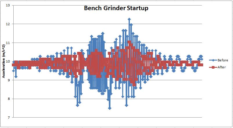
That looks a lot better!

In the future I am going to try to come up with a simple way to measure phase.  This might involve a computer instead of a cell phone, but for now I’m much happier with my bench grinder.   When it accelerates and decelerates it is much quieter and during operation you cannot tell it is running.  Hey, its not a Baldor, but it works like one now!

You can view the spreadsheet I used to do the calculations: BenchGrinderAnalysis.

X2 Mini Mill Vibrations and Chatter

Author’s Note:  I would like to thank Dr. Timber Yuen.  The analysis I did below was directly learned in his Machine Dynamics course as part of my degree in Manufacturing.  Dr Yuen’s practical problem solving teaching is a refreshing and needed approach where many engineering students are ‘drowning’ in math and not able to solve real world problems.

myx2

The Sieg X2 Mini Mill is know for the wet noodle characteristics of the column.  In particular the tilting column variation of the X2 (the most common variation) has extreme chatter and vibration issues when trying to take anything more than very small depths of cut in steel.  The reputation is such that Little Machine Shop has removed the Sieg’s tilting option on its mills in order to improve rigidity.

The other day I was single point fly cutting some tall plates with the Sieg X2 (no, I didn’t strip the plastic gears … yet) and noticed the column vibration was very significant.

I decided I should investigate what was going on.  Information on additional column support on the X2 is very plentiful around the web and I could have simply manufactured some form of column brace based on the modifications others have done.  But I wanted to learn more about the vibration issue before I went directly to a solution.  I though, hey that mill column looks a lot like a simple spring – mass – damper system.  The spring, well that’s the column, the mass – that’s the spindle housing and motor, and the damping – well there shouldn’t be much.

Firstly, I wanted to figure out what the natural frequency the column vibration.  How do you do this?  Most times an accelerometer would be mounted to the column.  I didn’t have an  accelerometer handy.  Or did I?  I started to think about the smart phone I owned.  Most smart phones have accelerometers built in.  I downloaded some software that retrieved data from the accelerometer, attached my phone to the column (zip ties work – electrical tape works well but leaves sticky glue on your screen!) and proceeded to strike the column with a dead blow hammer on the spindle housing in the Y direction and plot the response.

x2cell

I plotted the response in Excel.  The output from the accelerometer was in m/s².  I used the phone’s Z axis output only.

x2vibresponsebefore

Now is probably a good time to comment a little about the sample rate from the accelerometer.  My cell phone is an inexpensive Alcatel Pixi.  The maximum sample rate from the accelerometer I could achieve is 100 Hz.  This is why the above chart looks choppy.  I would have preferred something higher – say 500 Hz, but the data is good enough to make some general observations.

From the graph I found the period of the vibration to be 0.03941 seconds.  The inverse of the period is the frequency, which is 25.374 Hz.  25.374 Hz is 1522 rpm.  From this point on some math is involved, you can view it in the spreadsheet posted below.  If you want me to detail the math used, send me an email.  The mass was approximated using the mass of the spindle head and 0.23 x the mass of the column.  Using the data the following are calculated:

Damping Factor 0.110491
Natural Frequency 25.53079 Hz
Natural Frequency 160.4147 rad/s
Weight 45 lbs
Mass 20.45455 kg
K (spring rate) 526354 N/m
C (damping) 12.65826 kg/s

The low amount of damping is expected.  The low K value had me scratching my head a bit so I decided to calculate what the K value should be based on a fixed cantilever beam.  I estimated the moment of inertia using a square tube.  Again, I’ll spare the detailed math.

Ixx (Moment of Inertia) 1.68 in^4
Ixx 699268.795 mm^4
Ixx 6.99269E-07 m^4
Length 17 in
Length 431.8 mm
Length 0.4318 m
Young’s Modulus 12000000 psi
Young’s Modulus 82737120000 N/m^2
Calculated K 2155846.764 N/m
Weight 45 lbs
Mass 20.45454545 kg
Calculated Natural Frequency 324.6489688 rad/s
51.66948815 Hz
3100.169289 rpm

Whoa!   That’s a lot higher than what we measured!  What does this mean?  Something must be adding to the ‘springiness’ of the system.  I concur with most around the web that the large titling interface isn’t very good.

X2rearnut

Now before we go into improving the stiffness of the system, we should ask ourselves why we are doing it.  When I was single point flycutting, I was fly cutting at an RPM of around 500 – 600 rpm.  This is about 10 Hz.  Our measured natural frequency of the system is 25 Hz.  This condition where we are applying a load and taking it off is type of rotating unbalance problem.  The frequency ratio, simply the operating frequency divided by the natural frequency, gives an indication how close you are to resonance, and helps you figure out what the machine response will be.  In this case the frequency ratio, or r, is 0.4.  What does this mean?  Well avoiding all the math, a quick chart for rotational unbalance, (from Dr. Yuen’s spreadsheets – thank you!) gives a more clear picture:

VibrationAmplitude

At 10 Hz or r = 0.4 and zeta = 0.1 we are approaching the sharp peak where r = 1.  That’s really bad!  And the force chart shows the same story:

RotatingUnbalance

Since I really can’t do anything about the damping in the system I want to try to increase the stiffness of the system and thus operate at a lower frequency ratio, r.  Since the calculated stiffness should be closer to 50 Hz, I decided to fabricate a plate and mount it on the column, as well as add additional support for the base.  If you want additional pictures or drawings of the bracket send me an email and I’ll try to get them to you.

x2bracket

The bracket allows the mill to be trammed in the X direction, but removes the titling ability.  I never really used it anyway.  When I made the bracket I scraped it as flat as I could.  After installing I trammed the mill in the X and Y axis to within .0005″ (hence the shims).  I remounted my cell phone to the mill and determined the new natural frequency.

x2vibresponseafter

As you can see the data is becoming more choppy.  This is due to the increased frequency and the 100 Hz limitation by my phone.  From the graph I found the period of the vibration to be 0.022 seconds with the inverse or frequency to be 45 Hz.  That’s better!  The rest of the math shakes down below.

Damping Factor 0.089214
Natural Frequency 45.5025 Hz
Natural Frequency 285.9006 rad/s
Weight 45 lbs
Mass 20.45455 kg
K (spring rate) 1671937 N/m
C (damping) 13.64477 kg/s

The damping factor stays about the same (small change is due to experimental error!).

What type of improvement will you see with this?  Take my fly cutting scenario.  The new frequency ratio is 10 Hz / 45 Hz = 0.2.  From the rotating unbalance chart above if you move from r = 0.4 (where we were) to r = 0.2 the displacement decreases by a factor of over 5!  That is a pretty large reduction in displacement.

In conclusion, as many know already, the standard titling arrangement with 36 mm nut is not the best setup.  Adding a bracket or additional support is required.  At least now I have a quantifiable reason why.

You can download the spreadsheet if you want to: X2VibrationAnalysis.